

Beam Steerable and Frequency Reconfigurable Antenna Array for 5G Mobile Networks
Muhammad Farooq, Shahid Bashir* and Salman Ilahi Siddiqui

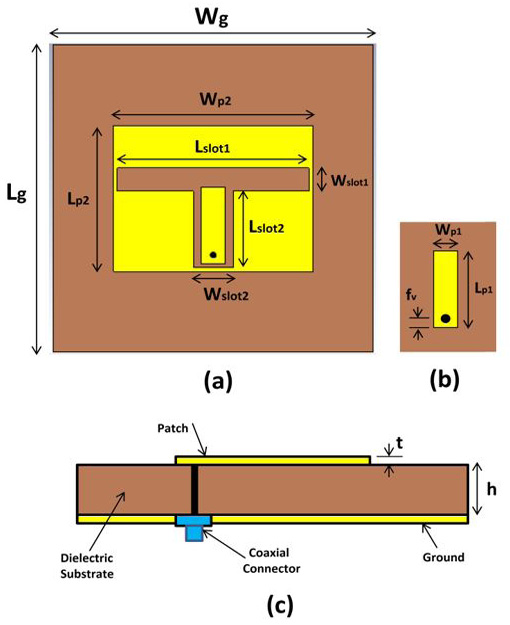
Figure 1:
Proposed Antenna element. (a) Front view of antenna element (b) Inner patch of antenna element (c) Side view of antenna element.
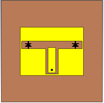
Figure 2:
Antenna element with switches.

Figure 3:
1x8 element array.
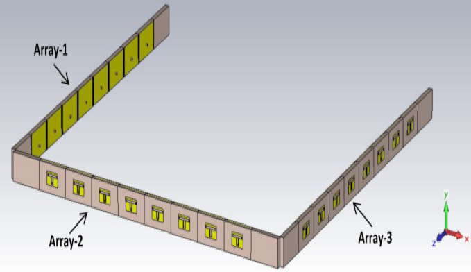
Figure 4:
Proposed beam steering antenna array.
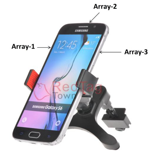
Figure 5:
Prospective position of proposed array in typical mobile phone.
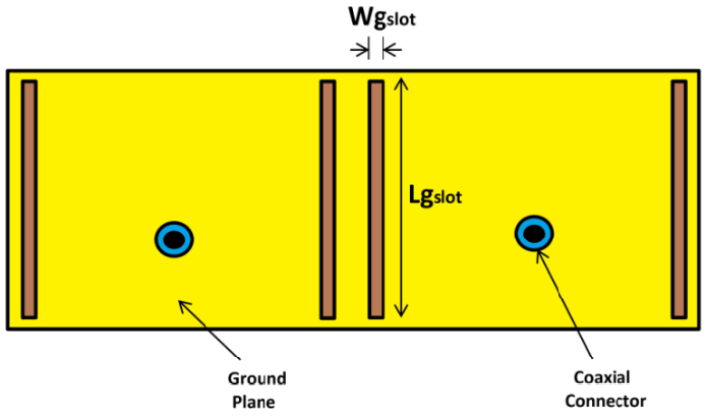
Figure 6:
DGS at the ground plane between two elements.
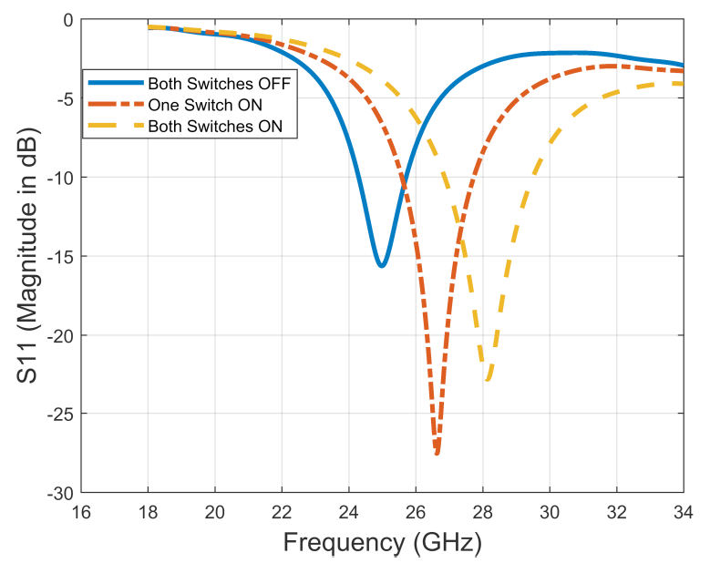
Figure 7:
Return loss of single element.
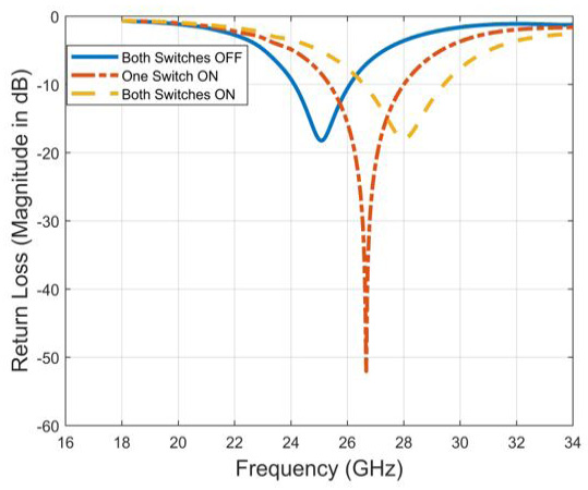
Figure 8:
Return loss for the proposed antenna.
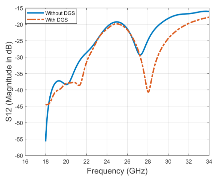
Figure 9:
Mutual coupling between two elements by turning OFF both switches.
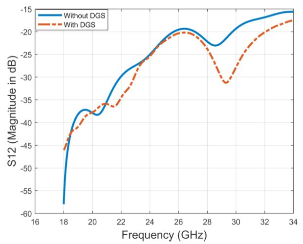
Figure 10:
Mutual coupling between two elements by turning one switch OFF and one ON.
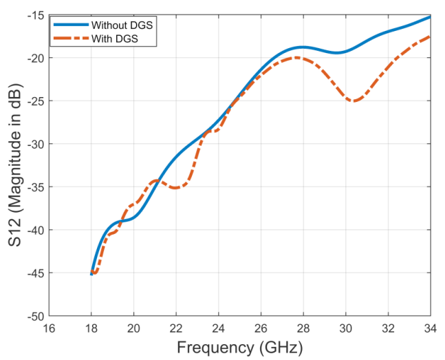
Figure 11:
Mutual coupling between two elements by turning ON both switches.
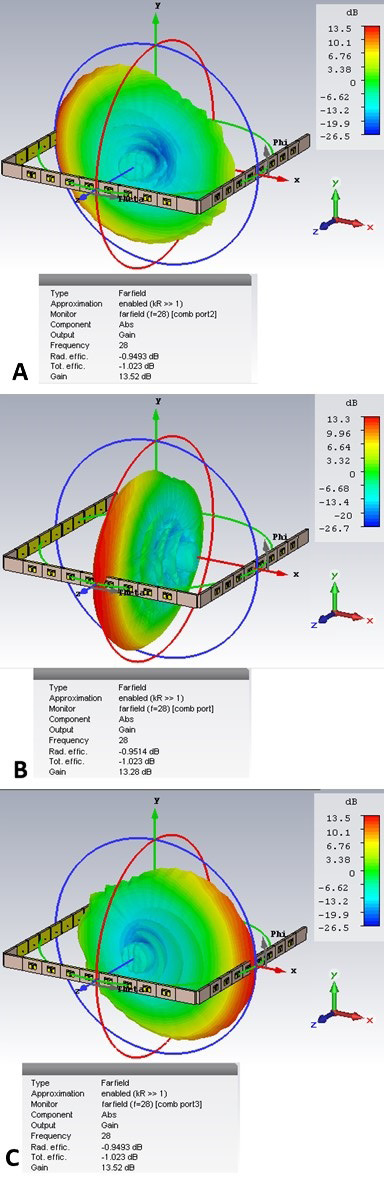
Figure 12:
Simulated Radiation pattern; (a) Only Array-1 excited; (b) Only Array-2 excited; (c) Only Array-3 excited.
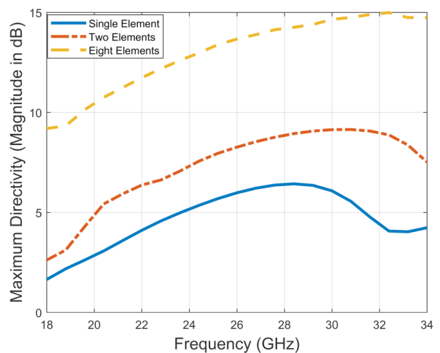
Figure 13:
Maximum Gain vs Frequency.
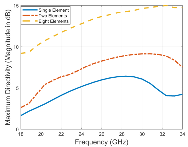
Figure 14:
Maximum Directivity vs Frequency.

June 2020
Vol. 39, Iss. 1, pp. 01-126

